

We often get asked: “You’re using a plastic housing and double-sided tape to attach your sensors. How is that robust, and doesn’t it affect accuracy?”
Let’s unpack that in practical terms.
Understanding Sensor Robustness: It’s All About Dynamics
To answer the question, it’s important to understand how our sensor behaves dynamically. Inside the sensor, the MEMS accelerometer is mounted directly to the housing, minimizing the distance between the measurement point and the structure it's monitoring.
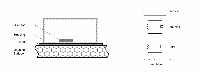
Between the machine surface and the accelerometer, there are two layers:
- A 1 mm layer of carbon-reinforced plastic (the housing)
- A 0.1 mm layer of double-sided tape
The whole setup can be modeled as a mass-spring system, where:
- The mass is the sensor assembly (approx. 9.5 grams)
- The springs represent the stiffness of both the housing and the adhesive layer
These two springs act in series, which is key when analyzing how motion is transmitted from the machine to the sensor.
Estimating Stiffness: Housing vs. Tape
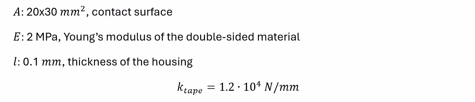
We estimate the stiffness of each layer based on simple tension/compression mechanics:
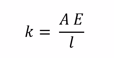
Based on the formula above, the stiffness of the housing is
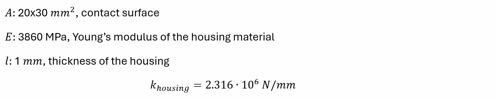
We can do exactly the same for the tape
Because the tape is softer, it deforms more under the same force. But how much does that actually affect the measurement?
How Much Error Does It Introduce?
Now, if we want to know how much error both the housing and tape would introduce, we only need to look at their respective deformation.
The deformation of the tape scales with applied force which is product of the housing mass and the acceleration of the machine. Because the spring are in series, they both feel the same force. It is also inversely proportional to their stiffness:

If we write the deformation as a sine function and differentiate it twice, we get the superimposed deformation acceleration, which distorts the measurement data.

The relative error can be calculated accordingly:

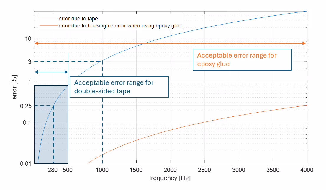
Looking at the graph below, we can see that the error scales quadratically with the frequency. The error due to the tape deformation stays below 0.25% up to 280Hz, below 1% at 500Hz and about 3% at 1kHz. The acceptable range differs from application to application but if you want to be below 1% of engineering error, double-sided tape is safe up to 500Hz.
If we were to replace the double-sided tape by an epoxy glue, the stiffness of the intermediate medium would be 10x higher than the stiffness of the housing. In that case, the error of the housing deformation would be representative for the total error. Hence, an epoxy glue attachment covers the full frequency range.
But What About Vibration Attenuation?
Up to now, we only considered the static behavior. A mass-spring system also acts as a second order low-pass filter. This means that after a certain frequency, the vibrations of the machine are no longer transferred to the sensor itself.
We can calculate the cut-off frequency with this formula:

This is the corresponding plot:
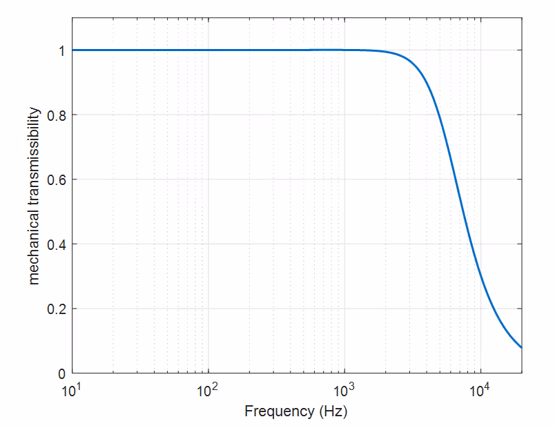
The plot of the transmissibility shows that the glue no longer transfers the vibrations and starts to attenuate them. The attenuation is already at 30% at 5.6 kHz and will increase further with the frequency.
Again, using epoxy glues will push this cut-off frequency drastically as it the housing stiffness is the dominant factor. In that case, it increase to 78kHz well beyond the range of interest.
What About Damping?
Damping describes how quickly vibrations die out. It's difficult to measure precisely in this setup, but some rough guidelines are:
- Housing (carbon-reinforced plastic): Loss factor ≈ 0.01 → very low damping
- Double-sided tape: Loss factor ≈ 0.1 → moderate damping
Even so, the energy lost to damping is minimal, especially when the structural deformation is already small. In practice, damping in the tape actually reduces measurement errors slightly by smoothing out sharp resonances.
Conclusion
It is an excellent choice to work with fiber-reinforced plastics because they result in a very low overall sensor mass. A lower mass leads to minimal deformation under dynamic loading, meaning that the sensor housing itself does not introduce measurable error in the vibration signal.
In the measurement setup using Forcebit sensors, the primary factor affecting measurement accuracy is the stiffness of the adhesive layer. As shown, using double-sided tape introduces less than 0.25% error up to 280 Hz, which is acceptable for most applications. For higher frequencies, a stiffer adhesive like epoxy will do the job perfectly.

.jpeg)