

Measuring torque directly on a rotating shaft is challenging, yet essential to boost your machine performance, durability and energy efficiency. In this post, I’ll briefly elaborate the challenges of the status quo in the first section and how our Forcebit torque sensor provides a cleaner, more reliable alternative in the second section.
The status quo solution: gluing strain gauges on a shaft
We start by stating the relationship between torque T and strain ε:

where R is the radius of the shaft, J is the polar moment of inertia which also depends on the radius (R4) and G is the shear modulus.
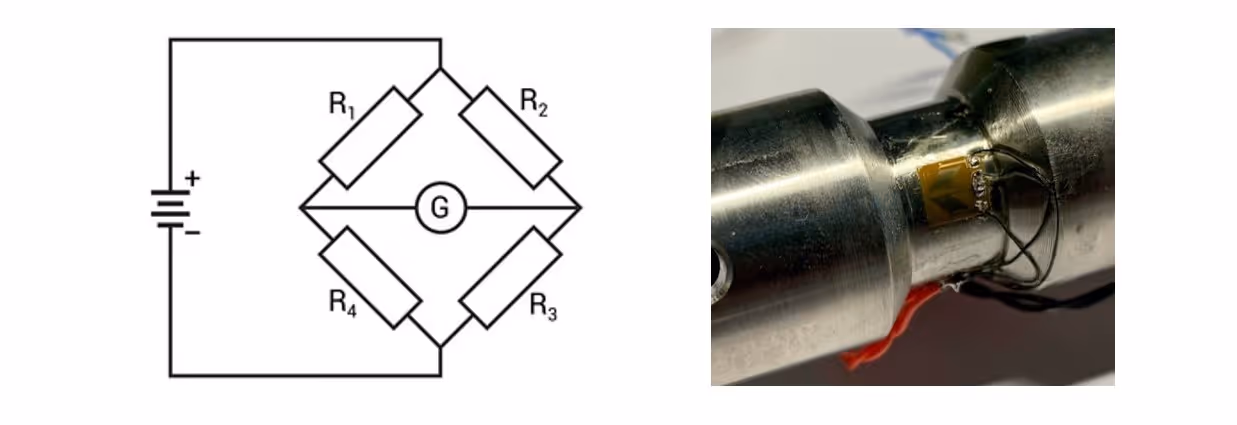
Measuring strain is done with a Wheatstone bridge and the output is proportional to the excitation voltage Vexctitation and the gauge factor GF which is typically 2. Because the output voltage is very small, it is increased by an electronic amplifier Gamplifier.

However, this setup brings several challenges:
- Since the bridge output is heavily amplified, even small errors in the gauge resistors—caused by heating, misalignment, pre-stretching, or poor soldering—can create large measurement errors.
- Installing strain gauges directly on the shaft is a delicate, time-consuming process requiring skilled technicians. If the shaft is already installed in the machine, surface preparation and gluing become even more difficult.
- Industrial shafts are often oversized relative to their torque loads, leading to very small strains and therefore low sensitivity. Manufacturers sometimes address this by locally weakening the shaft, as shown in the figure above.
Once the gauge is installed and producing readings, calibration becomes essential because each term in the equation above can deviate in practice. For example:
- The excitation voltage may drop due to wire resistance between the bridge and the power source.
- Differences in temperature dependency between gauges in the bridge cause drift in the measurement.
The Forcebit approach: a clamp-on torque sensor
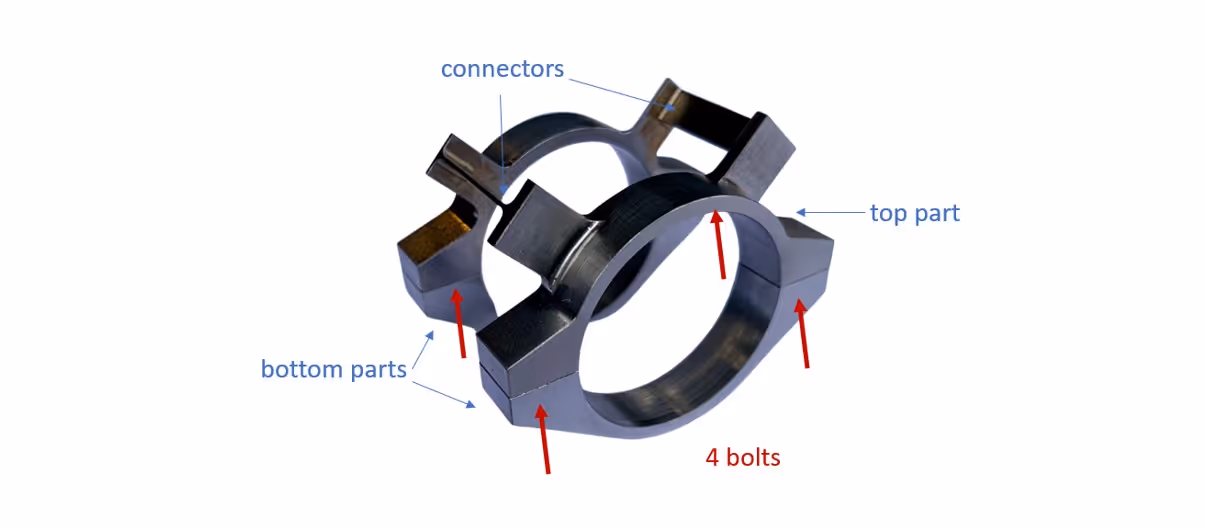
At Forcebit, we tackle these issues with a new approach, a clamp-on torque sensor. The concept is simple: the sensor acts as a very soft spring in parallel with the shaft. When the shaft twists under torque, the sensor deforms in the same way. However, because the sensor is much more flexible than the shaft, its additional stiffness is negligible, typically between 0.1% and 0.01% of the shaft stiffness.


A practical example is shown below for a 30 mm diameter shaft. The sensor includes a top section with two connectors that deform with the shaft, and a bottom section that clamps onto the shaft via a bolted joint. Custom strain gauges are positioned on these connectors to maximize output signal for a given torque.
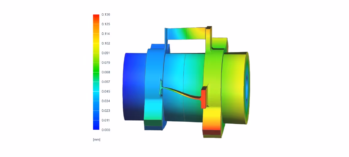
The design is developed using non-linear finite element analysis (FEA) to simulate both the clamping contact conditions and the connector deformations.
Although the concept is straightforward, practical implementation comes with significant challenges. We focused on three key design aspects:
- Mounting independence: The clamping procedure must not affect the measurement. Our design ensures that once the bolts are sufficiently preloaded, any further change in bolt torque has negligible influence on the sensor reading.
- Maximized sensitivity: The deformation is concentrated in the connectors (where the strain gauges are placed), while the rest of the structure remains rigid. This ensures high sensitivity without structural compromise.
- Rejection of non-torsional loads: The geometry minimizes the effect of bending, axial, or radial loads on the torque reading.
Of course, many other details go into our design, but we’ll keep a few of those to ourselves. 😉
The benefits: accuracy, reliability, and convenience
Our patented approach delivers significant advantages in all key areas:
Accuracy
The sensor geometry allows the torque sensitivity to be tuned simply by adjusting component dimensions. Because the strain gauges are positioned slightly above the shaft surface, the deformation is mechanically amplified, improving signal-to-noise ratio. Any temperature dependencies can be compensated with a simple calibration procedure, ensuring accurate results.
Reliability
Since the sensor is built and calibrated at the manufacturer’s site, the adhesive bonding can be oven-cured under controlled conditions. The wiring is kept as short as possible to reduce noise and voltage drop, and the gauges are integrated on a single patch instead of multiple separate components. These features greatly enhance long-term reliability.
Convenience
The traditional, painstaking process of gluing gauges directly to the shaft is eliminated. Installing the Forcebit sensor requires only four bolts and takes less than 15 minutes — even with the shaft already in place.
Want to know how our add-on torque sensors deliver higher sensitivity than directly mounting strain gauges on a shaft? Discover more in our latest blog post.
Now, you might ask how this compares to classical inline torque sensors. That’s a story for another time. and if you’re interested, we’ll be happy to write a follow-up post.
.jpeg)