

Lorem ipsum dolor sit amet, consectetur adipiscing elit. Suspendisse varius enim in eros elementum tristique. Duis cursus, mi quis viverra ornare, eros dolor interdum nulla, ut commodo diam libero vitae erat. Aenean faucibus nibh et justo cursus id rutrum lorem imperdiet. Nunc ut sem vitae risus tristique posuere.
Lorem ipsum dolor sit amet, consectetur adipiscing elit. Suspendisse varius enim in eros elementum tristique. Duis cursus, mi quis viverra ornare, eros dolor interdum nulla
Key Takeaways
- Multiple gateways, synchronised over PTP, raise the sampling rate. Giving each sensor its own gateway adds receiving capacity, while PTP keeps all data streams on a shared time base.
- Higher sampling rates improve the accuracy of our Kalman filters. More measurements per second give sharper estimates of angular position, velocity and acceleration, especially at high shaft speeds.
- The campaign is a concrete step towards measuring transmission error. On the LMSD gearbox, the shaft profiles matched closely, with an estimated transmission error of about ±1° on the slow shaft.
For our second measurement campaign on the LMSD gearbox testbench, we returned with an updated measurement setup: two gateways instead of one.
With a single gateway, we could sample two sensors simultaneously at 4 kHz. By giving each sensor its own gateway, we can now sample both at 8 kHz, while synchronising their data using the Precision Time Protocol (PTP).
The aim of this campaign was to obtain more accurate estimates of angular position, velocity and acceleration. These measurements help us understand the dynamic behaviour of the gearbox and take another step towards measuring transmission error.
In this post, we explain how higher sampling rates support that goal, demonstrate the results and discuss their relevance to industrial applications.
Transmission Error and Gearbox Dynamics
In an ideal gearbox, the output shaft follows the input shaft exactly according to the gear ratio. In practice, small deviations occur. The difference between the actual output angle and the angle predicted from the input rotation is known as transmission error.
Measuring this difference requires accurate, synchronised angular measurements on both shafts. Angular velocity and acceleration provide additional insight: they reveal how the motion varies over time and help identify recurring components in the shaft dynamics.
Our development therefore focuses on continuously improving our high-resolution encoder and its estimation algorithms. Higher resolution allows us to describe smaller angular changes, while improved accuracy helps us determine how reliably those changes represent the actual shaft motion.
This work supports two related ambitions:
- Measuring transmission error by comparing the input and output shaft positions while accounting for the gear ratio.
- Estimating torque from shaft twist by measuring the angular difference between two positions along a shaft and relating it to the shaft’s torsional stiffness.
The latter requires a suitable measurement arrangement and knowledge of the shaft’s mechanical properties. It is a further application we are working towards, rather than a result demonstrated in this gearbox campaign.
For both applications, small angular differences matter. Improving the measurement and estimation accuracy is therefore central to our development, and increasing the sampling rate is one way to achieve this.
The Use of Multiple Gateways and the Effect of Sampling Rate on Accuracy
Our sensors use Kalman filtering to estimate angular position, velocity and acceleration. The filter combines incoming measurements with a model of the motion and continuously updates its estimates.
By increasing the sampling rate from 4 to 8 kHz, we provide our Kalman filters with twice as many measurements per second. This enables more accurate estimates of angular position, velocity and acceleration, giving us greater insight into the gearbox dynamics.
This is particularly valuable at higher rotational speeds, where the shaft moves through a larger angle between successive samples. A higher sampling rate reduces that interval, helping us capture more detail in the motion and follow rapid variations more closely. It does not automatically double accuracy, but it provides a stronger basis for improving the estimates.
More capacity through multiple gateways
To accommodate the higher data rate, we distributed the sensor data across two gateways.
This approach gives us flexibility: the additional receiving capacity can support more sensors simultaneously or the same number of sensors at a higher sampling rate.
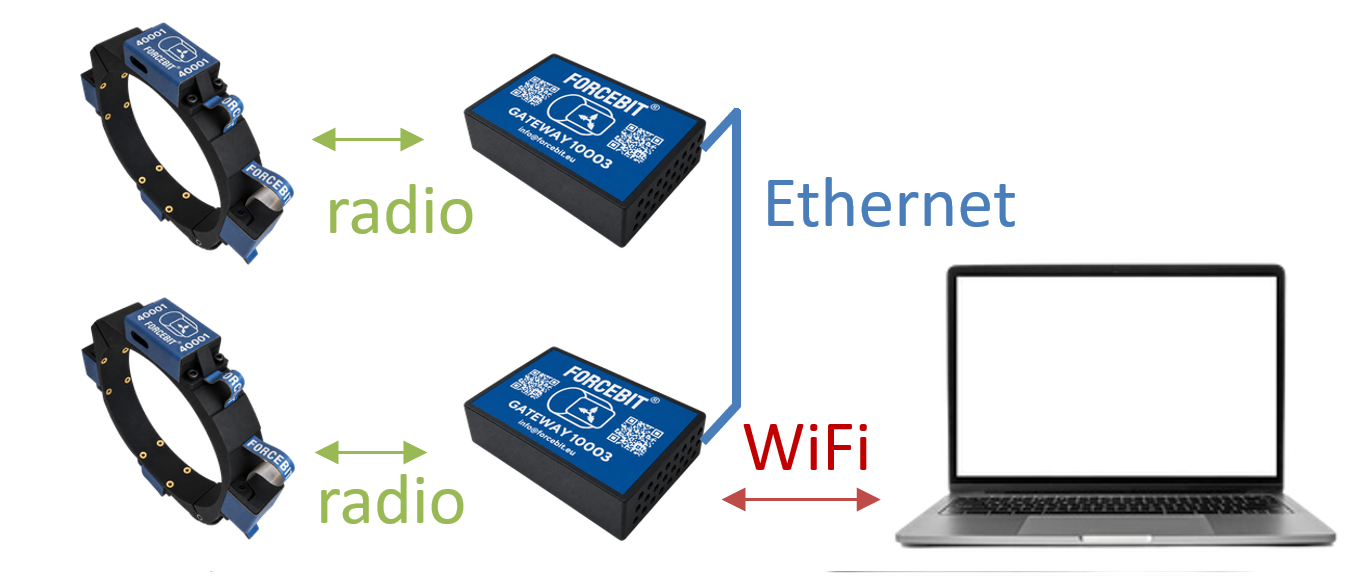
Receiving data through separate gateways also requires a common time reference. Even a small timing offset can appear as an angular difference between rotating shafts and distort the estimated transmission error. We therefore synchronise the gateways using PTP. This allows us to combine the two sensor streams on a shared time basis and compare the shaft movements.
Demonstration
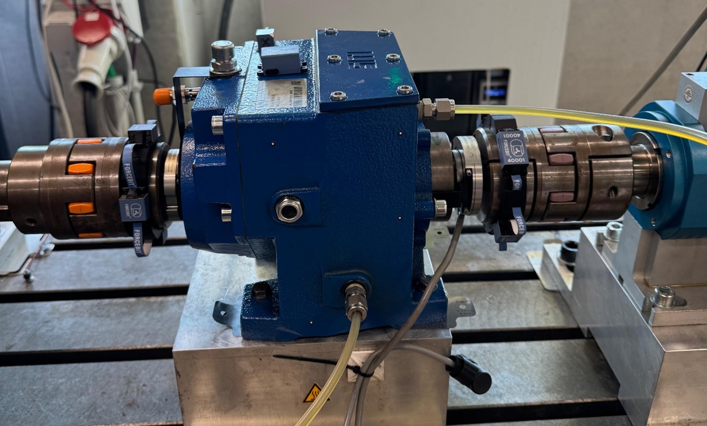
We tested the updated setup on the LMSD parallel-shaft gearbox, measuring the driving and driven shafts. The gearbox has a reduction ratio of approximately 32:1.
To compare the movements, we referred the slow-shaft measurements to the fast-shaft side using the gear ratio. For the angular-position comparison, we also accounted for a common angular reference.
After accounting for the gear ratio, the estimated angular position and velocity profiles show strong visual agreement.
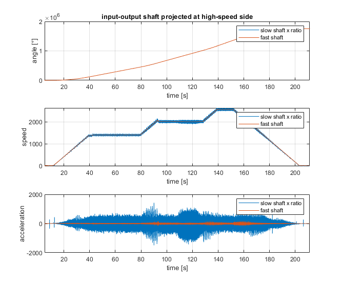
The speed profile of the slow shaft reveals ripple superimposed on the overall motion. We interpret this ripple in the present measurements as part of the drivetrain dynamics. Capturing these variations is important: they provide information that would be lost if we considered only the average rotational speed.
The acceleration signal provides a further view of these rapid variations. Frequency analysis of this signal can help identify recurring components and investigate possible resonances in the system.
By subtracting the corresponding shaft estimates, we can examine the deviations more directly. In this campaign, we observed:
- An estimated transmission error of approximately ±1°, referred to the slow-shaft side.
- A rotational-speed difference of approximately ±2–3 rpm, referred to the slow-shaft side.
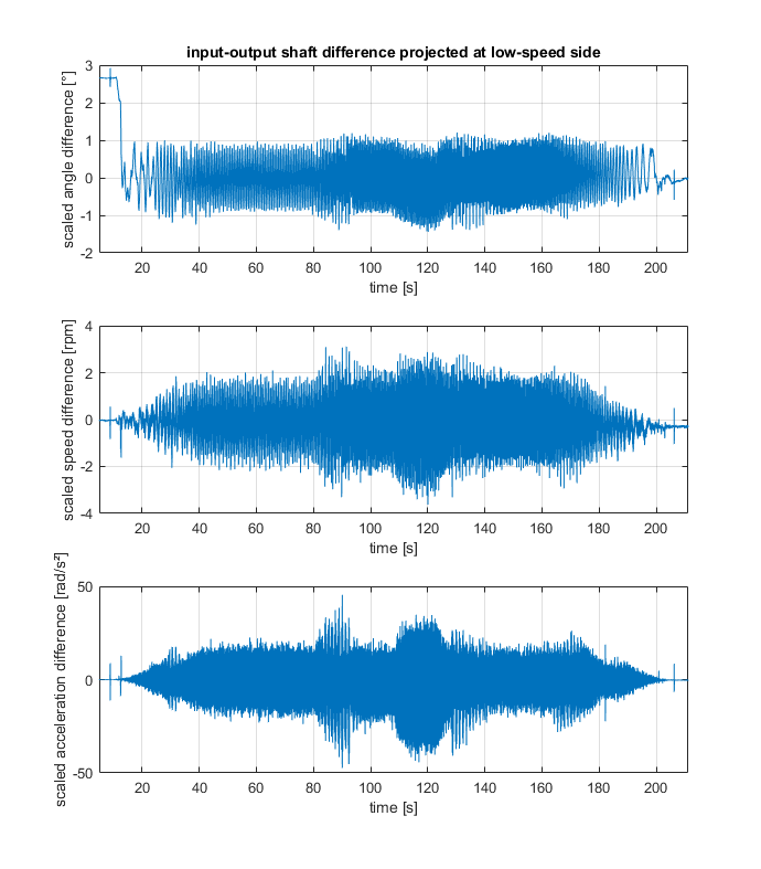
These values describe the estimated differences between the shafts in this experiment. They do not, by themselves, quantify the absolute accuracy of the sensors.
At the start of the measurement, the estimated angular difference is larger and then decreases as the gearbox begins to rotate. This is consistent with the Kalman filter gaining additional information from the motion and refining its initial estimate.
Relevance to industrial applications
More accurate angular measurements make it easier to investigate how a gearbox transmits motion and how its behaviour changes with operating conditions.
Combining angular position, velocity and acceleration provides a basis for studying transmission error, examining vibration components and tracking changes in dynamic behaviour under comparable conditions.
This second campaign at LMSD is a step towards those applications. Synchronised gateways enable higher sampling rates, and the additional measurements help our estimation algorithms resolve the shaft motion in greater detail, bringing us closer to reliable transmission-error measurements.
Conclusions and Next Steps
This measurement campaign demonstrates how synchronised gateways enable higher sampling rates, providing more information for our algorithms to estimate angular position, velocity and acceleration. This is an important step in our ongoing work to improve measurement accuracy and understand gearbox dynamics.
However, absolute measurement accuracy has not yet been validated. The results are promising, but further validation is needed before we can confidently quantify transmission error. A comparison against the existing encoders on the testbench is planned to establish the accuracy of our estimates.
At Forcebit, we will continue refining our algorithms and measurement system. Our ambitions include resolving small shaft twists over short distances, enabling torque estimation from torsional deformation.
We will share an update once the encoder comparison and accuracy validation are available. Stay tuned!
.jpeg)