

Choosing the right accelerometer is never about selecting the sensor with the “best” specifications on paper.
Every accelerometer is ultimately a trade-off between bandwidth, measurement range, sensitivity, synchronization, sensor mass, power consumption, throughput and cost. The correct choice therefore completely depends on the application and on which physical phenomena actually need to be measured.
At the same time, it is important to understand that there is rarely one single “perfect” accelerometer for a specific application category.
The boundaries between applications are often fluid. Most condition monitoring setups use data from a single sensor, but some may also require synchronization. A modal analysis setup may also benefit from lightweight wireless sensors when cabling becomes a disturbing factor, while moving systems may still require relatively high vibration bandwidths. Likewise, some MEMS accelerometers are now capable of performance levels that were traditionally associated only with piezoelectric systems.
As sensor technologies continue to evolve, the overlap between different accelerometer categories becomes increasingly large.
The goal is therefore not to rigidly classify applications into one sensor type, but rather to understand which trade-offs matter most for the specific measurement problem.
A sensor optimized for high-frequency shock measurements will usually perform poorly for extremely small low-frequency vibrations. Conversely, a lightweight wireless MEMS sensor designed for moving systems solves completely different problems than a bulky piezoelectric accelerometer used for modal analysis.
The key question is therefore not: “Which accelerometer is best?”
but rather: “Which trade-offs matter most for this specific measurement?”
Application-Driven Sensor Selection
Different applications place completely different requirements on the sensor system.
Extremely Small Low-Frequency Deformations
Some applications focus on extremely small and very low-frequency structural deformations.
Examples include:
- deformation of linear guideways
- deformation of ring gears caused by passing planets
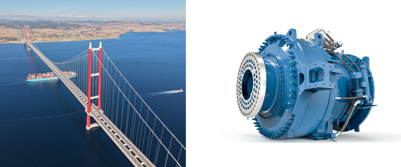
- monitoring of bridges or buildings
- slowly varying structural loading
In these systems, sensitivity, stability and low-frequency accuracy are far more important than extreme bandwidth.
The challenge is not measuring large accelerations, but detecting very small changes accurately over long periods of time. For these applications, seismic accelerometers or highly accurate low-noise MEMS accelerometers are often preferred.
Impact and Shock Measurements
Impact measurements form a completely different category.
They typically require very high bandwidths, very high measurement ranges and fast transient response.
Applications such as drop testing, crash testing, ballistic environments and machinery impacts can easily require hundreds or even thousands of g’s combined with bandwidths extending into tens of kilohertz.
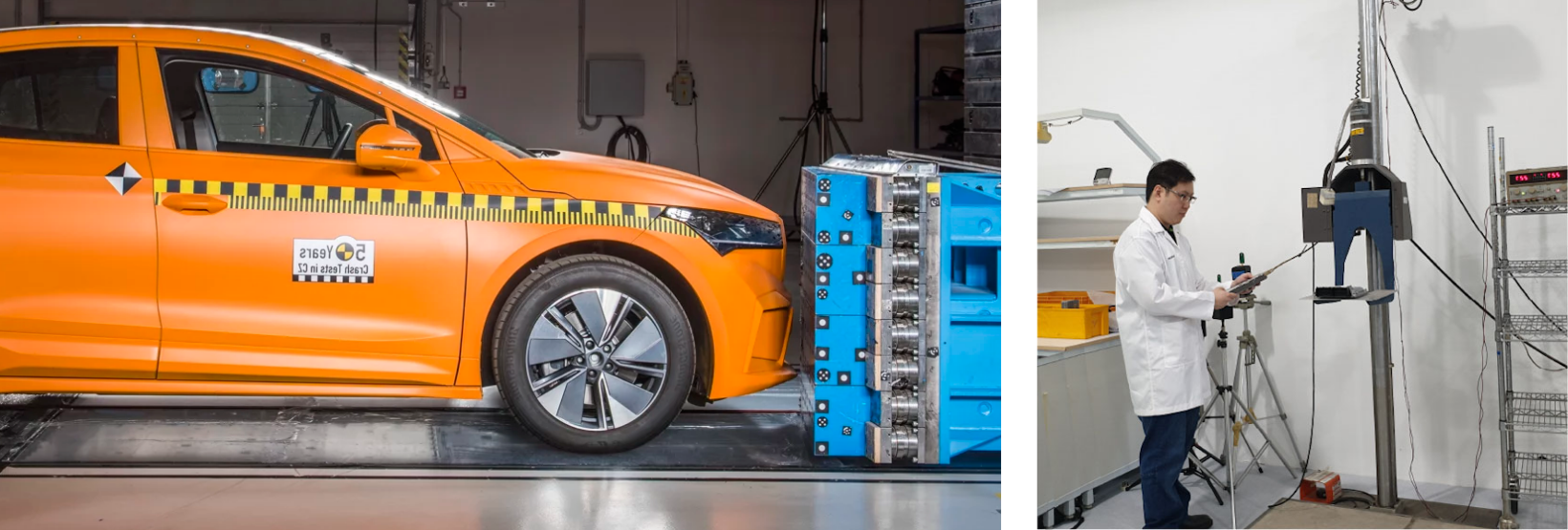
In these systems, survivability and dynamic range become more important than small-signal accuracy.
Modal Analysis and Frequency Response Measurements
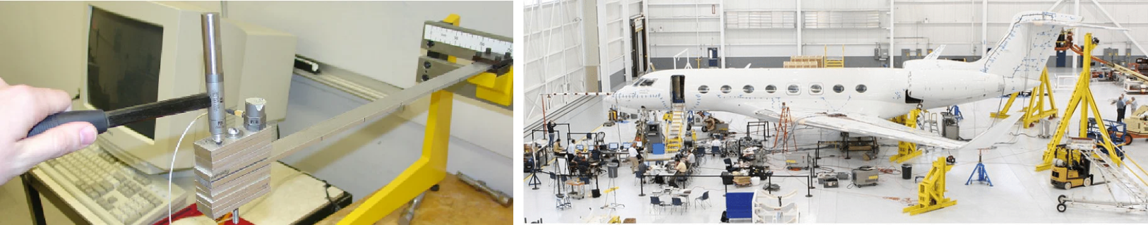
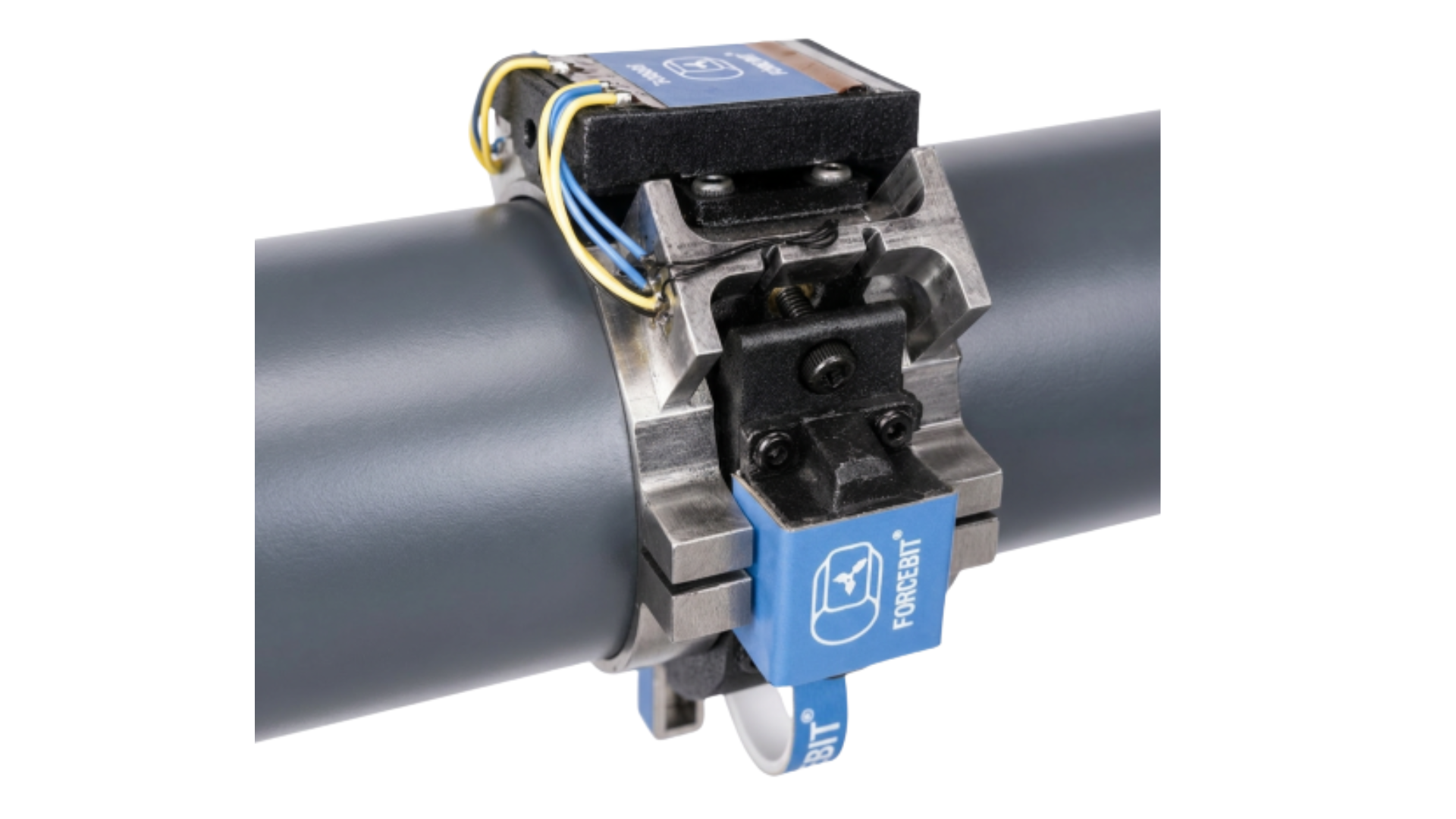
Modal analysis introduces another important challenge: the interaction between the sensor and the structure itself.
For lightweight flexible structures such as thin plates, printed circuit boards, composite structures, acoustic structures or lightweight precision components, sensor mass becomes extremely important.
A sensor that is too heavy can significantly alter the dynamic behavior of the structure being measured. This effect is known as mass loading.
In such cases, one also needs to be mindful about the cable because the cable itself can influence the measurement.
This becomes especially important for structures below roughly one kilogram, where the sensor itself may already represent a meaningful percentage of the total mass.
For larger industrial structures, this becomes less critical.
Besides bandwidth, synchronization and timing accuracy are also essential for modal analysis. Small timing errors between sensors directly affect phase measurements and mode shape calculations.
As modal measurements are typically excited by a hammer or shaker, synchronization between the input force signal and the accelerometer measurements becomes critical. Even small timing offsets directly influence the calculated frequency response functions.
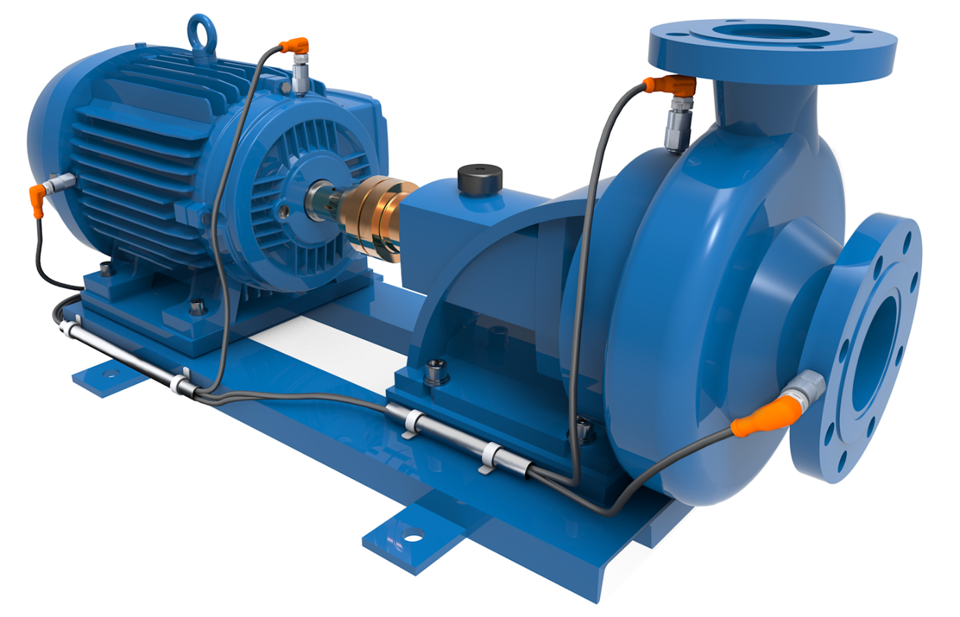
Condition Monitoring and Rotating Machinery
Condition monitoring applications are strongly driven by the frequency content that needs to be measured.
Here, the focus is mainly on gear mesh frequencies, bearing defect frequencies and ball pass frequencies. These frequencies can often be estimated upfront and should be used to determine the required bandwidth.
For lower-speed rotating systems, bandwidths up to roughly 5 to 10 kHz are often sufficient for industrial or automotive gearboxes, pumps, fans and general industrial machinery.
The rotational speed of the driving shaft already provides an important first indication of the required frequency range.
However, high-speed applications require significantly higher bandwidths, often extending toward 20 kHz or even 30 kHz. Typical examples include spindle measurements, electric motor drives, turbo-compressors and turbines.
As rotational speed increases, the vibration content rapidly shifts toward higher frequencies. In these applications, piezoelectric accelerometers are often preferred because of their superior high-frequency performance.
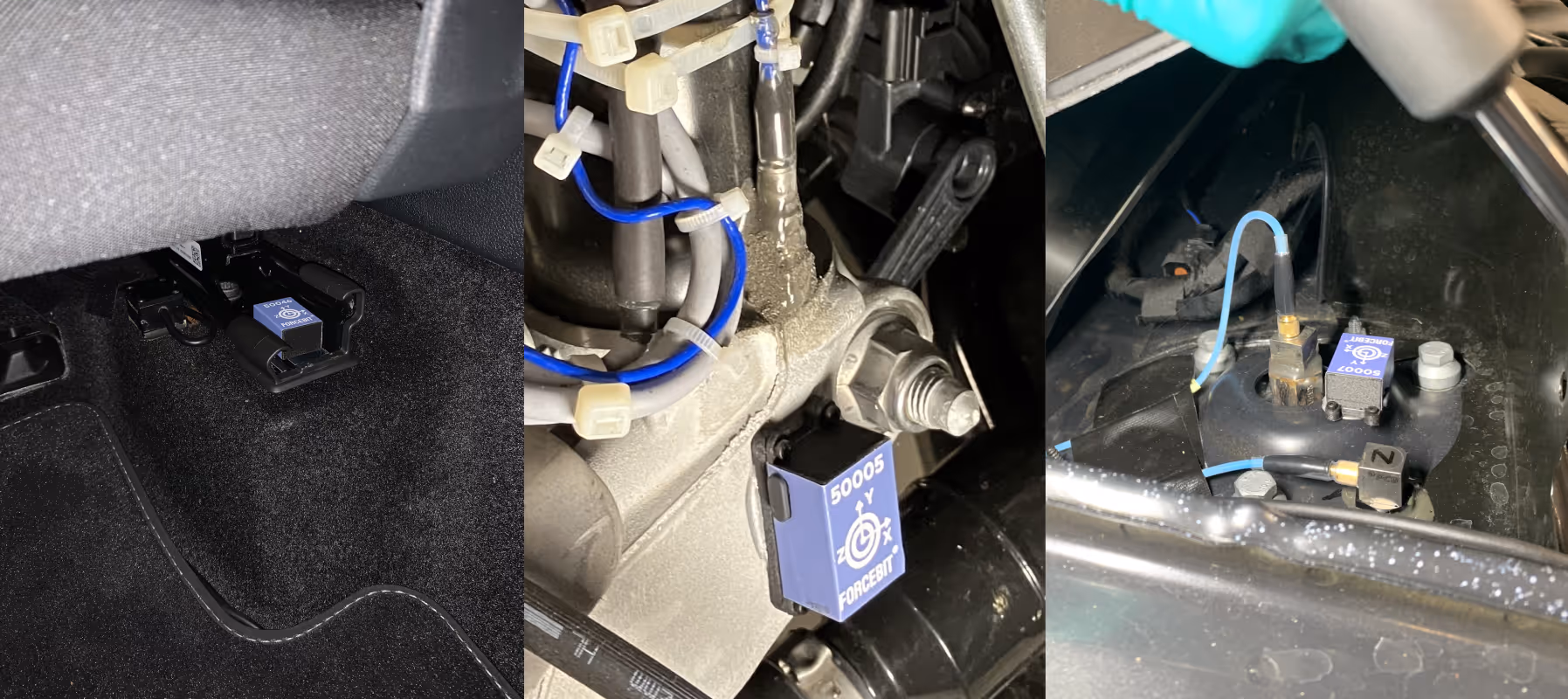
Moving Systems
Another important category consists of moving systems such as gantry systems, robotics, linear drives, vehicles, bicycles and biomechanical applications involving humans or animals.

These systems introduce an additional challenge: large rigid-body motion.
Traditional wired accelerometers can become problematic because the cables themselves may influence the measurement through cable forces, cable vibrations, routing constraints and limited mobility.
In highly dynamic systems, the cable can sometimes become a larger source of disturbance than the sensor itself.
When multiple sensors are used simultaneously on moving systems, lightweight synchronized wireless systems can provide major advantages.
This creates a growing need for systems that combine low sensor mass, synchronization, wireless operation and sufficient bandwidth within a compact form factor.
Traditional high-end piezoelectric systems often provide excellent bandwidth and accuracy, but become less practical once mobility, cabling or sensor mass become limiting factors.
At the same time, many low-cost wireless MEMS systems prioritize simplicity and battery life over synchronization accuracy or dynamic performance.
This is also the area where synchronized wireless MEMS accelerometer platforms such as those developed by Forcebit can provide a strong balance between mobility, synchronization and vibration performance.
The Most Important Accelerometer Specifications
Once the application physics become clear, the relevant accelerometer specifications naturally follow.
In practice, accelerometer selection is rarely driven by a single specification. Most real-world systems require balancing multiple competing constraints simultaneously.
Bandwidth
Bandwidth determines which frequency content can still be measured accurately.
Typical low-cost MEMS systems are often limited to a few hundred hertz up to roughly 1 or 2 kHz. Higher-end MEMS accelerometers can extend toward bandwidths around 10 kHz or more.
Piezoelectric accelerometers are typically preferred for high-frequency vibration measurements because of their superior mechanical bandwidth, often extending well beyond most MEMS capabilities.
Seismic accelerometers, on the other hand, are usually optimized for extremely low-frequency measurements and often operate within bandwidths of only a few hundred Hz.
The required bandwidth is therefore directly linked to the physics of the system being measured.
Measurement Range
The measurement range determines the maximum acceleration the sensor can measure.
Low-range sensors generally provide higher sensitivity, lower noise and better small-signal resolution, while high-range sensors are required for shocks, impacts and highly dynamic systems.
Increasing measurement range generally reduces sensitivity and small-signal performance.
Accuracy and Resolution
Resolution alone does not determine measurement quality.
Real-world accuracy is often dominated by sensor noise, temperature stability, drift, linearity and cross-axis sensitivity.
These parameters are usually clearly specified in high-quality datasheets. If this is not the case, the real-world performance may be less predictable.
For low-amplitude measurements, these aspects are often far more important than raw sampling rate specifications.
Synchronization
Synchronization becomes critical whenever multiple sensors are used simultaneously.
Timing accuracy directly affects phase relationships between channels in dynamic systems, and even relatively small timing errors can introduce significant measurement errors.
The required synchronization accuracy is strongly linked to the measurement bandwidth. For low-frequency measurements below roughly 100 Hz, synchronization errors in the millisecond range may already be acceptable.
High-end wired acquisition systems can achieve synchronization accuracies down to the microsecond level. Lightweight wireless synchronized MEMS systems typically operate in the range of several microseconds to tens of microseconds, depending on architecture and communication strategy.
Sensor Mass
For lightweight structures, the mass of the accelerometer itself may influence the dynamics of the structure.
This effect, known as mass loading, can become critical in modal testing, PCB measurements, lightweight structures and precision mechanics.
Compact lightweight sensors therefore become essential in many applications.
Lightweight teardrop piezoelectric accelerometers can weigh below 1 gram, while many industrial piezoelectric sensors typically weigh between 5 and 15 grams.
Wireless systems are often significantly heavier because of batteries, housing and wireless electronics, although recent lightweight wireless MEMS platforms are increasingly reducing this gap.
Different Accelerometer Categories
Because applications vary so strongly, different accelerometer technologies have emerged that each optimize different engineering trade-offs.
Low-Cost DIY MEMS Systems
At the lowest end of the spectrum are simple MEMS-based systems built around microcontrollers, analog MEMS sensors, evaluation boards or even smartphone sensors.
Typical bandwidths range from a few hundred hertz up to roughly 1 or2 kHz.
These solutions are attractive when cost is the dominant factor and when synchronization, bandwidth and accuracy requirements remain relatively limited.
They are often ideal for education, prototyping and basic monitoring applications.
Wireless WiFi/Lora Sensors
Wireless WiFi and LoRa vibration sensors have become especially popular in industrial condition monitoring.
These systems are typically optimized for relatively high sampling rates combined with local edge processing, feature extraction and cloud connectivity.
Some systems can achieve bandwidths extending toward roughly 24 or even 36 kHz. The trade-off is that high-throughput measurements can often only be sustained for limited periods because of power consumption and wireless throughput constraints.
Instead of continuously transmitting all raw data, these systems frequently process vibration information locally and only transmit summarized health indicators, alarms or spectral features.
This significantly reduces network load while still enabling continuous monitoring.
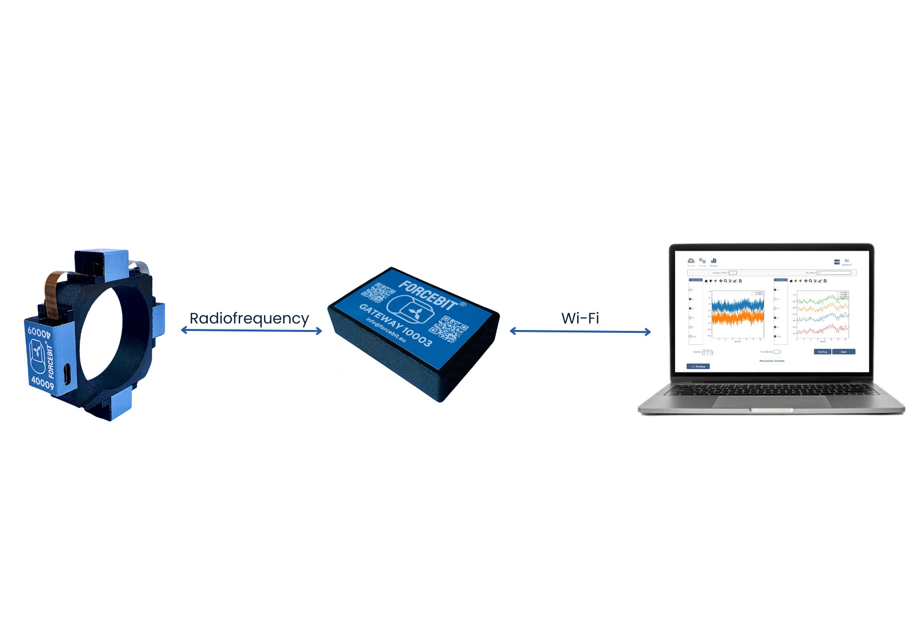
Wireless Bluetooth/Radio Frequency Sensors
Bluetooth accelerometers typically focus more strongly on low cost, energy efficiency, compactness and ease of deployment.
Very low-cost Bluetooth systems are often limited to bandwidths around 100 Hz. Industrial-grade Bluetooth systems more commonly operate around1 kHz, while higher-end synchronized wireless systems can extend toward 4, 8 or even 16 kHz depending on implementation.
Achieving such bandwidths typically requires a combination of BLE with proprietary synchronization and radio architectures rather than relying on standard Bluetooth communication alone.
The trade-off is that Bluetooth systems generally provide lower throughput and shorter communication range compared to WiFi-based solutions.
However, they remain extremely attractive for mobile measurements, temporary measurements, biomechanics, wearable systems and low-cost monitoring applications where battery lifetime and deployment simplicity are critical.
By default, wireless sensors are generally not synchronized. If synchronization is supported, this is typically a key advertised feature of the system.
MEMS Accelerometers
MEMS accelerometers aim to balance several sensor characteristics simultaneously.
Modern high-performance MEMS accelerometers can achieve surprisingly good bandwidth and synchronization performance while remaining compact and energy efficient. Depending on the design, some MEMS accelerometers can extend toward bandwidths around 10 kHz or more.
An important distinction within MEMS systems is the difference between bare MEMS chip designs and fully integrated packaged sensor systems.
The MEMS sensing element itself is only one part of the final performance.
The surrounding electronics, PCB layout, filtering, grounding and mechanical integration often have a major influence on noise, thermal stability, bandwidth, cross-axis sensitivity and overall measurement quality.
As a result, two systems using the same MEMS sensing chip can still show very different real-world performance.
Piezoelectric Accelerometers
Piezoelectric accelerometers remain the standard solution for high-frequency vibrations, bearing diagnostics, rotating machinery and modal analysis.
Their key strength is superior high-frequency behavior combined with excellent dynamic performance.
Bandwidths can extend significantly beyond those of most MEMS accelerometers, making them particularly attractive for high-speed rotating machinery and high-frequency vibration analysis.
The trade-off is that they cannot measure static acceleration and are less suited for ultra-low-frequency measurements.
Seismic Accelerometers
Seismic accelerometers are optimized for extremely low-frequency measurements, ultra-low noise and very high precision.
These sensors are often larger, more expensive and require more power, but provide exceptional low-frequency performance.
Their bandwidth is typically limited to a few hundred hertz because they are specifically optimized for very small low-frequency signals.
They are typically used for highly specialized precision measurements and structural monitoring applications.
Conclusion
The “best” accelerometer does not exist.
The right accelerometer is simply the sensor whose trade-offs best match the physics of the application.
Understanding what frequencies matter, how much acceleration must be measured, whether synchronization is required and how important sensor mass or mobility become is far more important than comparing datasheet specifications alone.
In vibration engineering, the sensor itself is part of the measurement system.
The best results are therefore achieved when the accelerometer technology, integration strategy and application physics are all considered together.
One more thing...
Accelerometer selection is often easier when the application requirements are first translated into a structured list of constraints such as bandwidth, measurement range, synchronization accuracy, sensor mass and mobility requirements.
This article can therefore also be used as a practical evaluation framework when comparing different accelerometer solutions.
Many engineers today additionally use AI-based tools to help evaluate sensor datasheets, compare trade-offs between technologies and identify potential limitations in a measurement setup. When doing so, it is important to provide the AI system with sufficient application context rather than asking for a generic “best sensor.”
The quality of the sensor selection process ultimately depends on how well the application physics and measurement constraints are understood.
Image References
1. Suspension bridge image
Source: Wikipedia — https://en.wikipedia.org/wiki/Suspension_bridge
2. Wind turbine gearbox image
Source: Windpower Monthly — https://www.windpowermonthly.com/article/1806069/ngc-leap-torque-density-fully-integrated-18mw-offshore-wind-powertrain
3. Crash test laboratory image
Source: Škoda Storyboard — https://www.skoda-storyboard.com/en/skoda-world/a-modern-crash-test-lab-can-handle-all-kinds-of-tests/
4. Drop test setup image
Source: CentiForce — https://centiforce.com/test-lab/drop-test
5. Cantilever modal analysis setup
Source: ResearchGate — https://www.researchgate.net/figure/Modal-analysis-experimental-setup-for-the-cantilever-beam_fig1_267305475
6. Aircraft modal analysis image
Source: ResearchGate — https://www.researchgate.net/figure/Modal-analysis-of-an-airplane-model-2_fig1_309488278
7. Industrial pump image
Source: IFM — https://www.ifm.com/in/en/shared/technologies/real-time-maintenance/centrifugal-pump
8. Industrial robot image
Source: KUKA — https://www.kuka.com/nl-be/producten/productiesystemen
9. Electric vehicle image
Source: Škoda — https://nl.skoda.be/
.jpeg)